
Investigation of Heat Transfer for the Wall between Polyurethane Foam and Polystyrene
Ali Reza Taheri Fard*
Department of Civil Engineering at Peter the Great Saint-Petersburg Polytechnic University, Russia
*Corresponding author: Ali Reza Taheri Fard, Department of Civil Engineering at Peter the Great Saint-Petersburg Polytechnic University, Russia
Article History
Received: June 15, 2021 Accepted: July 15, 2021 Published: July 21, 2021
Citation: Taheri Fard AR. Investigation of Heat Transfer for the Wall between Polyurethane Foam and Polystyrene. Int J Eng Tech & Inf. 2021;2(3):83‒87. DOI: 10.51626/ijeti.2021.02.00018
Abstract
In construction, polyurethanes are used to make high-performance products that are strong yet lightweight, perform well, durable and versatile. Polyurethane products can also help improve the aesthetic design of homes and buildings. Polyurethane is a key ingredient in several types of high-performance insulation materials, sealants and adhesives used in home and building construction. Here I will show the difference between using polyurethane foam and polystyrene using the example of a 1.5 m high wall and different widths depending on the thickness of the polyurethane.
Introduction
Further progress in the development of new models and designs of power oil transformers and shunt reactors to ensure reliable operation for 20-30 years requires the improvement of various systems of their internal and external (external) cooling [1]. With the modern thermal calculation of power transformers, the local, average and maximum temperatures of the windings and the temperature of the oil in the channels of the windings, as well as the excess of the temperatures of the windings over the temperature of the oil, should be determined, taking into account the variable thermophysical properties of the cooling medium and the dependence of losses in the coils of the windings on temperature [2-4]. Thermal processes in power transformers must be taken into account in the optimal design and development of new types of transformers, and they are still not well understood in transformer construction. The temperature level determines the rate of degradation and aging of the insulation, the service life of the transformer, the reliability of its operation and the likelihood of emergencies. If electro-magnetic calculations can be performed with a relative error of several percent, then when calculating the temperature field, the winding of transformers in various operating modes, the error can in some cases be tens of percent [3-6]. in addition to the geometric parameters and current loads used in electrodynamic calculation, there are also the temperature of the cooling medium, data on thermal loads, for each concentrate also the dimensions of the vertical channels, the thickness of the insulating cylinders, the thermal conductivity coefficients of the cylinders, and parameters of the external cooling system for each type of load. Earlier, the method of equivalent heat circuits (ETC) was widely used for thermal calculation of power transformers and shunt reactors [7]. With its help, by replacing complex multidimensional domains in continuous media with heat circuits with concentrated thermal conductivities and thermal capacities described by systems of ordinary differential or algebraic (for stationary problems) equations, it is possible to significantly simplify and accelerate the solution of complex problems [8]. Today, these calculations no longer meet modern requirements for the accuracy and completeness of determining the temperature field, especially the location and value of the value of the maximum winding temperature at the hottest point (HHT) [9].
CFD for Simulation
Modern CFD modeling programs allow calculating air movement patterns, temperature and humidity distribution, and determining the parameters of comfort in rooms, houses and buildings. This helps to more accurately design and optimize heating, ventilation and air conditioning (HVAC) equipment. In order to use CFD modeling with confidence in your design, you need to make sure that the numerical calculations reproduce the results of standard thermal engineering calculations. The heat conduction equation is solved and the temperature values are determined at all points of the model. Hydrodynamic calculation describes the movement of air. Additionally, the thermal radiation from surfaces and from the sun’s rays is calculated [10].
For the calculation, it is necessary to set the dimensions of the room, thermal conductivity and reflective properties of materials and boundary conditions: temperature at the beginning of the calculation and conditions at the boundaries of the model. Set up the grid and parameters of the convergence of the calculation.
Heat Transfer
Conductivity is a heat transfer mechanism in which energy is transferred between parts of the continuum due to the transfer of kinetic energy between particles or groups of particles at the atomic level. Conduction is an internal exchange of energy from one body to another, which is in perfect contact with each other. Thermal conductivity is the property of a material to conduct heat, which is evaluated primarily from the point of view of the Fourier law for thermal conductivity.
The Law of Thermal Conductivity, also known as Fourier’s Law, states that the rate of heat transfer through a material over time is proportional to the negative temperature gradient and the area perpendicular to the gradient through which heat flows.
Where q is the local heat flux density, K is the material conductivity, ∆T is the temperature gradient. Thermal resistance is a thermal property and a measure of the temperature difference by which an object or material resists heat flow. Thermal resistance is inversely proportional to thermal conductivity. Just as electrical resistance is related to the conduction of electricity, thermal resistance can be related to the conduction of heat [11]. Then Fourier’s law of thermal conductivity for the wall can be expressed as:
Material and Methods
The wall was investigated with a temperature of 22 degrees inside and -30 degrees outside. Wall convection was studied using transient and steady-state thermal conditions.
The height is 1500mm, length 2500mm and width are 350mm.
Results
Research shows that polyurethane foam and polystyrene foam have a good thermal insulation coefficient based on their coefficient of thermal conductivity. Figure 1 shows the total heat flux for polyurethane foam and foam as a function of temperature.The normalized value of the reduced resistance to heat transfer of the enclosing structure, R0norm, (м ·°С)/Вт, should be determined by the formula:
Where R0tp is the base value of the required resistance to heat transfer of the enclosing structure, m °C/W, should be taken depending on the degree-day of the heating period, (GSOP), °С·day/year, construction area and determine according to SP 50.13330.2012 [12].
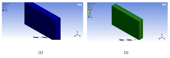
Figure 1: shows the total heat flux for (1) Polyurethane Foam (2) Polystyrene.
Based on the calculation, the heat transfer resistance for foam and polyurethane foam is 5.05 and 9.15(m· °C)/W, respectively. That is, both correlates well with SP 50.13330.2012, however, polyurethane foam shows better characteristics in the case of thermal insulation.
When we have calculated the heat flow, we can find the total heat loss for both walls, which will be calculated as the heat flow times the area. We will find that the total heat loss for polyurethane foam and plastic foam is 21.332 and 38.612W respectively, the lower the heat loss, the better the thermal insulation performance.
Transient thermal conductivity was carried out for both models to better understand the difference in thermal convection for both models: an internal coefficient of 10W/m2.c and an ambient temperature of 22 degrees, and an external coefficient of 30W/m2.c and an ambient temperature. temperatures of -30 degrees have been used (Figure 2).
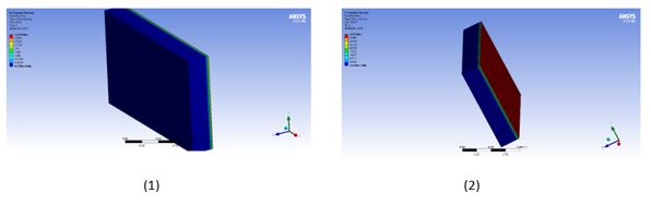
Figure 2: shows the total heat flux in transient thermal (1) Polyurethane Foam (2) Polystyrene.
During the temporary simulation, the polyurethane foam showed good temperature retention characteristics of 21.908 degrees, on the other hand, the foam showed good temperature retention characteristics over a time of 20.33 degrees. This demonstrates the excellent performance of the polyurethane foam.
Structural Factors
The use of strain limits is becoming more common in seismic design and wall evaluation. The deformation limits of the walls in existing design and assessment documents are verified using an extensive database.
A force of 50MPa is applied to the wall, which exceeds the normal force acting on the walls, in order to better determine the deformation for both models (Figure 3).
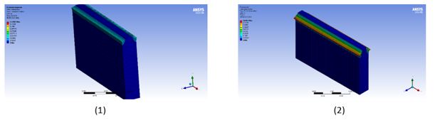
Figure 3: Shows deformation (1) Polyurethane Foam (2) Polystyrene.
The calculated deformation for foam and polyurethane foam is a maximum of 0.849 and 0.128, respectively, that the polyurethane foam shows good characteristics in case of deformation. Elastic limit is the highest stress that can be applied to it without causing plastic (permanent) deformation. When a material is stressed to a point below its elastic limit, it will return to its original length upon release of the stress. The calculation includes the maximum elastic deformation for both foam and polyurethane foam (Figure 4).
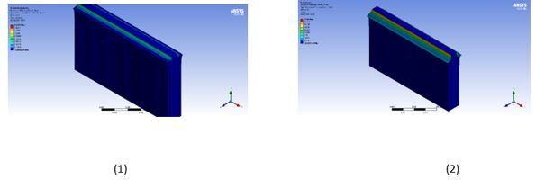
Figure 4: Shows the maximum elastic deformation for thermal (1) Polyurethane foam (2) Polystyrene.
The maximum elastic deformations for foam and polyurethane foam are 11.85 and 1.6325, respectively.
When designing structures and strength of materials, an element or component can be exposed to forces/moments of various types or their complex combination.
These forces and moments or their combinations cause different types of stresses at different points of the bar. Depending on the material of the element and the stress generated, the element may fail due to exceeding various types of stresses.
Therefore, it is imperative to know the failure mechanism of various types of materials so that the structure can be properly designed to prevent this stress from being exceeded at the critical point. Maximum principal stress theory states that failure of any material occurs when the principal stress in that material, due to any load, exceeds the principal stress at which failure occurs in a one-dimensional load test. And the main blow is given by:
Rankin formulated the theory of the maximum principal stress as follows: a material fails as a result of fracture when the highest principal stress exceeds the ultimate strength σu in a simple tensile test. That is, at the beginning of the texture.
The maximum principal stress for foam and polyurethane foam is 1.3196e8 Pa and 1.3035e8 Pa, respectively, which shows a good result for determining stress (Figure 5).
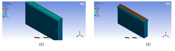
Figure 5: Shows the maximum principal stress for (1) Polyurethane Foam (2) Polystyrene.
Optimal Width for Polyurethane Foam
At the moment, we understand that polyurethane foam in its characteristics is much better than foam in the case of thermal insulation and construction. We are now going to compare the different widths of the polyurethane foam for the project. 4 different widths of 50, 70, 80, 100mm were modeled and studied (Figure 6).
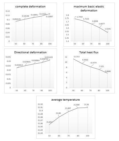
Figure 6: 4 different widths of 50, 70, 80, 100mm were modelled and studied.
Regarding the comparison of different widths, the author recommends a width of 60mm + the required width for conductive reinforced concrete, as it meets the thermal insulation regulatory requirements and shows a satisfactory result of deformation, shear stress and deformation. Considering that the bulk density, kg/m3 is 50, the weight of using polyurethane foam for a wall with dimensions 1500 * 2500 * 270 mm is 22.5kg.
References
- Ali Reza Taheri Fard (2020) Influence of Vegetation on Shear Stress and Flow Rate in Open Channel using Flow3D. Civil Eng Res J 9(5): 555774.
- Lockwood FC, Shah NG (1981) A new radiation solution method for incorporation in general combustion prediction procedures. International Symposium on Combustion 18(1): 1405-1414.
- Thermal bridges in building construction – Linear thermal transmittance-Simplified methods and default values. EN ISO 14683: 2008.
- Requirements and specifications for zero energy houses, passive houses and mini-energy houses. FEBY 12, Sweden’s center for zero energy houses.
- Sherman MH (1987) Estimation of infiltration from leakage and climate indicators. Energy and Buildings 10(1): 81-86.
- Fard ART, Soheili H, Movafagh SR, Ahmadi PF (2016) Combined Effect of Glass Fiber and Polypropylene Fiber on Mechanical Properties of Self-Compacting Concrete. Magazine of Civil Engineering 62(2): 26-31.
- Janssen H, Carmeliet J, Hens H (2004) The influence of soil moisture transfer on building heat loss via the ground. In Building and Environment 39(7): 825-836.
- Bligh TP, Willard TE (1985) Modeling the thermal performance of earth-contact buildings, including the effect of phase change due to soil freezing. Computers & Structures 21(1-2): 291-318.
- Rees SW, Cleall PJ, Li YC, Shao K (2013) Freezing soil effects on earth contact heat transfer. Building Services Engineering Research and Technology 34(3): 259-274.
- Spiga M, Vocale P (2014) Effect of Floor Geometry on Building Heat Loss Via the Ground. Heat Transfer Engineering. 35(18): 1520-1527.
- Martin K, A Erkoreka A, Flores I, Odriozola M, Sala J M (2011) Problems in the calculation of thermal bridges in dynamic conditions. Energy and Buildings 43(2-3): 529-535.
- Thermal Protection of Buildings. SNiP 23-02-2003, SP 50.13330.2012.