
Investigation of Press Forming Process for CF/PEEK and GF/PP Thermoplastic Composite Materials
Esma Nur Duran1, Yasemin Sumeyye Yildirimoglu1, Seda Ersoz1, Fahrettin Ozturk1,2*, Zafer Gemici3
1Turkish Aerospace Industries Inc., Turkey
2Department of Mechanical Engineering, Ankara Yıldırım Beyazıt University, Turkey
3Department of Mechanical Engineering, Yildiz Technical University, Istanbul, Turkey
*Corresponding author: Fahrettin Ozturk, Department of Mechanical Engineering, Ankara Yıldırım Beyazıt University, 06010, Turkey
Article History
Received: June 07, 2021 Accepted: June 10, 2021 Published: June 11, 2021
Citation: Duran EN, Yildirimoglu YS, Ersoz S, et al. Investigation of Press Forming Process for CF/PEEK and GF/PP Thermoplastic Composite Materials. Int J Eng Tech & Inf. 2021;2(3):53‒60. DOI: 10.51626/ijeti.2021.02.00013
Abstract
Aerospace industry requires engineering materials with significant mechanical strength, low cost, easy to recycle, easy to process, and high chemical resistance. Thermoplastic composites are considered as new generation aerospace structural materials due to their superior characteristics. In this study, one of the most common methods used in manufacturing of thermoplastic composite parts from unidirectional (UD) pre-consolidated prepreg (blank), press forming process is investigated and crack behavior of the samples is examined. The forming process is utilized, and consolidated blanks of UD CF/PEEK and GF/PP composite materials are shaped by pressing, and mechanical tests are performed. Micro defects on the samples are monitored by microscopic examination and scanning electron microscopy (SEM) analysis. Results show that when the temperatures of CF/PEEK and GF/PP blank are increased by preheating, the formability of both composites are enhanced. Final outcomes reveal that both CF/PEEK and GF/PP composite materials can easily be used for possible aircraft structures. Additionally, CF/PEEK is found to be appropriate not only secondary structures but also for primary structures.
Keywords: Composite materials; Thermoplastic composites; Carbon fiber; Glass fiber; PEEK; PP; Press forming; Composite testing
Introduction
The use of thermoplastic composites in aerospace, defense, energy, electronics, and automotive industries has been increasing rapidly. In addition to the mechanical properties being as good as traditional materials, thermoplastics attract attention due to their recyclability, no need for autoclaves, easy processability, easy repairing, light weight, easy weldability, etc. Due to that reason, there has been rapid growth in research and development activities, as well. The aerospace industry requires lightweight components with ultra-mechanical properties. So, the usage of advanced thermoplastic composite materials in high-performance structures, even in primary structures, of aircrafts have a great interest. In recent years, advanced composites have been replacing traditional structural materials in primary load-carrying aircraft structures to a significant extent, more than 50% advanced composites by weight [1].
Thermoplastic composites are a new group of materials compared with traditional materials, which possess outstanding characteristics and performances. Thermoplastics are materials of polymers that linked by intermolecular interactions (Van der Waals forces) and enlarged to regular structures. While they have the simplest individual molecular structures, which are held in place by weak secondary bonds and intermolecular bonds, the use of thermoplastics as a matrix makes them rather complex. They can be re-melted and reshaped under certain temperature and pressure conditions [2]. There has been a growing interest in composites having a thermoplastic matrix instead of traditional thermoset matrix. Thus, they have been increasingly replacing metals and thermoset composites materials in many sectors as being substitute. Although they were introduced to the market many years ago, they have started to find use in recent years with the further development of materials and the development of production technologies, such as thermoforming, fiber placement, press forming, welding etc. Thermoplastics are known to be able to recyclable because of being non-cross-linked polymers which can be heated, melted, and reformed by multiple cycles without having any damage. A great advantage of recycling enables waste utilization. Additionally, no-curing requirement makes their processing faster than thermoset composites processing, which causes short cycling as many times as desired [3]. In addition to having revolutionary light-weighting solutions, for aerospace structures, where weight reduction to reduce fuel consumption, thermoplastics composites come to the forefront with their advanced thermal, electrical, and mechanical properties (such as ultra-toughness).
Thermoplastic composites consist of high strength fibers and polymers. Continuous fibers provide high strength/load carrying capacity, while matrices hold the fibers together and allow local stresses to be transmitted between the fibers. The fibers can be E-glass, S-glass, Kevlar, boron and carbon fibers, while thermoplastic matrices can be PEI (polyetherimide), PPS (polyphenylenesulfide), PP (polypropylene), PEEK (polyetherketoneketone), etc. materials. High performance thermoplastic composites generally consist of polymers such as PPS, PEKK and PEEK, and carbon fiber reinforcements, and find use in the primary structural parts of an aircraft. In this study, the most widely used CF/PEEK was selected as high-performance thermoplastic composite for primary structures, while the most widely used GF/PP was selected as low-performance composite for secondary structures. The reason for working with materials in two separate segments is that the process is desired to be tested at both high temperatures and relatively low temperatures to see the press forming process’s extremums. Press forming is one of the methods commonly used in the production of thermoplastic composites [4,5]. Parts such as ribs, brackets, clips, stringers and stiffeners used in aircraft fuselage and wings can be produced by this method [6,7]. Generally, parts with a constant fiber orientation and constant thickness are produced by this method. Depending on the load, the production of the parts having different thicknesses and different orientations is quite limited. To realize such a production, the part-specific heating, transfer, forming, and cooling system must be designed and optimized.
In this study, the press forming method, which is widely used in aviation, was used, and experimental studies were conducted to determine the optimum operating parameters of the method for selected parts. The use of thermoplastic composites in aerospace industry for both primary and secondary aero structures were investigated experimentally.
Press Forming Process
Hot press forming which is also called thermoforming is one of the main manufacturing processes for high performance composite materials [8]. The process is a widely used industrial forming process using heat and pressure for thermoplastic composite materials [6]. In this study, the press forming process trials were carried out for both unidirectional (UD) cross ply quasi-isotropic carbon fiber (CF)/PEEK and glass fiber (GF)/PP consolidated plates. The laminated plate theory that characterizes the mechanical and thermal properties and performance of unidirectional quasi-isotropic laminates were used with the stacking sequence. In the case studies, a typical laminate consists of different numbers of plies at only θ ±45°, and 90°, which effectively resist unidirectional loads, and is reasonably dose to avoid distortion of the plate during the fabrication.
The experimental press forming system consists of a furnace, a hydraulic press, and a mound with a temperature controller. A simple demonstration of the system is shown in Figure 1. The furnace has a maximum heating temperature of 1,100°C with a control accuracy of 2°C. The maximum forming force of the press (in this study a screw-driven type tensile testing machine) is 100kN and the maximum stroke is 600mm. The range of forming speed was determined as 12 to 30mm/s. Consolidated plate test coupons having dimensions of 200mm in length, 40mm in width, and 2 mm in thickness by taking into account the size of a tool as shown in Figure 2, were cut from 300 mm x 400 mm plate by a water jet machine.
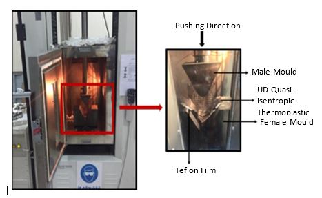
Figure 1: Experimental press forming system.
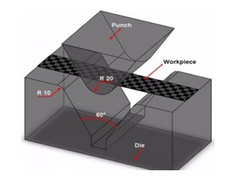
Figure 2: Male and female die set geometry for press forming process.
In the forming experiments, matched male-female sets constructed of steel were used (Figure 3). The die set was maintained at the range of 25-150°C for PP and 25-225°C for PEEK throughout the forming cycle. Coupon thickness control was maintained by incorporating a position where the specimen was tangent to the male tool. Prior to the forming process, the laminated composite specimen was put into the furnace for heating until the thermoplastic grains were in a melting state. In fact, the test pieces were rapidly raised to a maximum forming temperature which was approximately over 70°C of polymer’s melting temperature by taking into account the heat losses during the transportation between the heating environment and the forming station. The conditioned composite sample was quickly transferred from the furnace to the preheated mold. After the specimen was placed in the mold, the heated test piece was formed and consolidated under constant pressure and temperature for 3 min. Then, the specimen was replaced from the tool into the ambient environment to let it cool down. It was used a Teflon film that can withstand 50°C for easily removing the specimen from the mold. Figure 3 shows that there are obvious differences in the formed parts because of different process conditions.
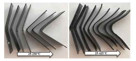
Figure 3: Thermoforming final product for GF/PP and CF/PEEK.
Table 1 & 2 indicate prominent processing parameters affecting the final performance. The most effective process parameters identified are the raw material blank forming temperature, the mold tool temperature, the forming speed, the holding pressure, and the process period. The whole forming period including preheating, transport, and forming were taken approximately between 10 to 15 min. Providing that the test pieces are mounted on a transport fixture, less than 10 minutes of overall process interval is achievable with the press forming. It can be deduced that the press forming process of thermoplastic composites has short cycle time with high efficiency, unlike processes of thermoset materials which have at least 7-8 hours of manufacturing durations [9]. So, it is an effective way to reduce manufacturing costs and achieve good reproducibility. On the other hand, the only disadvantage of this method is that the press applies pressure in only one direction, therefore, it is difficult to make complex-shaped (i.e., beads, closed corners, etc.) parts.
The best result was obtained for CF/PEEK trial at 225°C tool temperature, 425°C blank temperature with 30mm/min tool speed, for GF/PP trial at 150°C tool temperature, 230°C blank temperature with 21mm/min tool speed. However, the desired shape of the material was not obtained precisely. This may be since the use of inappropriate mold design or mold material, unexpected heat losses during the transportation to the chamber and, some anomalies in the pre-consolidated plate that originated from autoclave process or layup. To understand the reason, formed parts were examined by means of micro-cut in detail as shown in Figure 4 for CF/PEEK and Figure 5 for GF/PP.
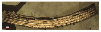
Figure 4: Micro-cut image of CF/PEEK.
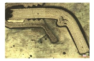
Figure 5: Micro-cut image of GF/PP.
It can be clearly seen that voids, delamination, and wrinkles were arisen after the forming process. There are various mechanisms causing wrinkles [10]. The results of micro-cut revealed that material was undergone wrinkles in the bending-zone which are very undesirable from the structural integrity point of view as a result of in-plane loading, geometry, stacking sequence, material stiffness, and material’s nonoptimized thermal history. In addition, the cause of wrinkles can be non-uniform resin distribution between the layers. In other words, resin-rich layers at elevated temperatures cause plies to slip relative to each other during the forming process. Another defect that was seen in micro-cut is buckling stresses generated in the plies during the deformation, which are functions of time, temperature, and processing rate. Black zones seen in the cross section in Figure 4 & 5 indicate voids which are defined as a concentration of the microscopic interfacial voids that are entrapped in the resin between fiber plies and dispersed throughout the thickness of the laminate. The presence of voids and porosity formation in composite laminates is mainly based upon trapped volatiles which may be caused by chemical composition, resin mixing and preparing procedures, tooling, laminate configuration, and moisture content [11-13]. Moreover, delamination was observed in the formed part which is portrayed as the separation of adjacent layers due to the weakening of the interface layer between them. Delamination generally is resulted from insufficient curing temperature, air pockets, and inclusions [14]. Even the existence of a crack that already occurred before may be initiated delamination in the interface.
Experimental Studies
In this study, mechanical testing of composite materials was carried out to determine the strength and stiffness of the prepreg used in forming process trials. The specimens were tested by using tensile and compression test methods as described in the following lines and INSTRON 5985 universal testing machine having a load cell of 250kN capacity as shown in Figure 6 was used in order to determine the mechanical properties before considering the forming process.
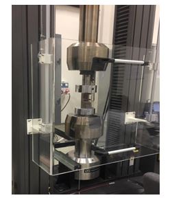
Figure 6: INSTRON 5985 universal testing machine.
Tensile testing is widely used to determine mechanical properties of materials [15]. The basic physics of most tensile test methods are very similar: a coupon with a straight-sided gage section is gripped at the ends and loaded in uniaxial tension [16,17]. Coupon cross-section and the load-introduction are the main differences between these tensile test coupons. The cross-section of the coupon may be rectangular, round, or tubular; it may be straight-sided for the entire length (a “straight-sided” coupon) or width – or diameter-tapered from the ends into the gage section (often called “dog bone” or “bow-tie” specimens). EN 2561 is the original standard test method for straight-sided rectangular coupons [16]. In general, the EN 2561 standards are preferred due to better control of testing details that may enable variability and also it is generally used for carbon fiber reinforced plastics-unidirectional laminates in the aerospace industry. According to the given explanations, in these experimental studies, we preferred EN2561 standard as the reference specimen preparation procedure [18]. For comparison, the tensile strength levels of different high performance materials used in aerospace industry are given in Figure 7.
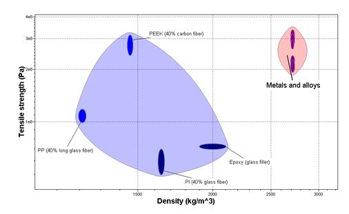
Figure 7: Comparing of high-performance engineering materials in aerospace industry for tensile strength.
Five samples of CF/PEEK and GF/PP were tested for each case at 24±1ºC room temperature (RT). The tensile performance was tested according to EN2561. During the tests, the tensile force which continuously accelerating was applied, simultaneously elongation of the specimen was recorded by favor of strain-gauge. Paper tabs were used for tensile coupons in the tests to prevent the possibilities of the damage because of the gripping force. The tensile specimen was held in a testing machine by wedge action grips and pulled at a recommended crosshead speed of 2mm/min. The tensile test data reported for both UD CF/PEEK and GF/PP in this study were obtained using 16 plies specimens with the stacking sequences of [(+45/-45/0/90)2]s, and 8 plies specimens with the orientation of [+45/-45/0/90]s. The specimens were cut from 300mm x 400mm autoclave cured panels which were produced using standard lay-up and vacuum bagging. The gauge length of the specimen was 120mm. A successful test must cause failure in the gauge region of the specimen. Failure at the tab edge (or gripped edge) or in the tab is unacceptable.
Compression Testing
The compressive testing method determines the in-plane compressive properties of polymer matrix composite materials reinforced by high-modulus fibers [19]. High performance materials in aerospace industry for compressive strength are shown in Figure 8 for comparison. Compression test is conducted on composite materials, using appropriate instrumentation to determine compressive modulus, ultimate compressive strength, or strain-at-failure. These properties are determined through the use of test fixtures that is typically designed to be as simple to use and fabricate as possible, to minimize stress concentrations, to minimize specimen volume, and to introduce a uniform state of uniaxial stress in the specimen test section [20]. Test fixtures play a critical role in compression testing so that compressive properties of thin composite laminates are difficult to measure owing to sidewise buckling of specimens.
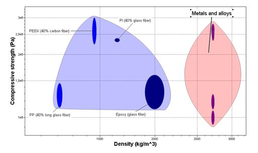
Figure 8: Comparing of high performance materials in aerospace industry for compressive strength.
Several test methods and specimen designs have been developed to overcome the buckling problem [16]. Enough restraint must be provided by the fixtures to prevent undesirable failure modes. However, if excessive, or slight restraint is used, the failure strengths may lead to artificially high or low results. The test was performed in accordance with ASTM D 3410, “Standard Test Method for Compressive Properties of Polymer-Matrix Composite Materials with Unsupported Gage Section by Shear Loading”, which is the most common standard in the aerospace industry [21]. The selection of a compressive test method depends on the material being tested, the test environment, and the goals of the testing program. This standard is applicable to composites made from unidirectional tape rather than a sandwich beam. Flat wedge surfaces ensure better contact between the wedges. Flat wedge grips can also tolerate possible variations in specimen thickness. The test fixture consists of two parallel guide pins in its bottom half and top half which pins help maintain good lateral alignment between these two halves during testing. The standard specimen length is 140mm, out of which the middle 10mm as the gauge length. The compression testing specimen was held in the testing machine by wedge action grips and compressed at the recommended crosshead speed of 1.5mm/min with the strain rate of 0.01min. Flat-straight sided coupons were used for the compression tests of fibrous composite laminas. Compression specimens were kept short by the aim of reducing the possibility of buckling failures as indicated in the standard. Dimensions for four specimens were 10 mm x 150 mm cut by a water jet machine. Strain gauges were mounted in the gage section to measure longitudinal and transverse strain data.
Results and Discussion
Tensile Test Results
4GF/PP tensile samples having 8 plies specimens with orientations of [±45°/0°/90]s and 4 CF/PEEK tensile samples having 16 plies specimens with the stacking sequences of [(+45/-45/0/90)2]s were tested. All the samples were cut by water jet machine and excess heat was not produced due to higher cutting speed. Tensile stress vs. strain results are shown in Figure 9 & 10.
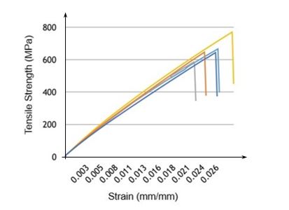
Figure 9: Tensile strength vs. strain for CF/PEEK.
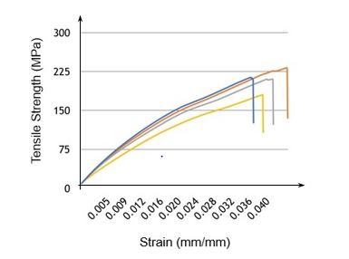
Figure 10: Tensile strength vs. strain for GF/PP.
The tensile strength, modulus of elasticity, and strain results were calculated and summarized in Table 3-5.
During the test of UD CF/PEEK and UD GF/PP, some of the identical specimens had some failures in the gripping region as shown in Figure 11.
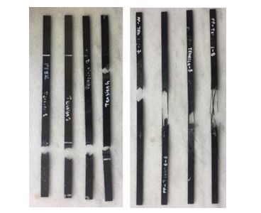
Figure 11: Tensile specimens after the fracture.
Failure in the gripping region can be due to the random distribution of flaws in the specimens. May be because, specimens were manufactured as a trial product, resulting in slightly non-homogeneous thickness of the samples throughout the panel. Vacuum, pressure, and smoothness of aluminum tool during hand lay-up have slight effects on the homogeneity. The maximum tensile strength and modulus were recorded at 0°. However, with increasing fiber orientation angle and their combination, both tensile strength and modulus were reduced. To compare the fiber orientation, UD [0]s CF/PEEK consolidated plate had 1850 MPa tensile strength whereas average tensile strength of four specimens UD [±45°/0°/90°/±45°/0°/90°]s CF/PEEK consolidated plate was recorded as 636 MPa as shown in Table 4. In view of material types, it can be clearly seen that UD [±45°/0°/90]s GF/PP consolidated plate had a much lower modulus of elasticity and tensile strength value than UD [±45°/0°/90°/±45°/0°/90°]s CF/PEEK consolidated plate. Therefore, considering all the results, GF/PP composites were deemed unsuitable for using primary structure in aerospace applications. Tensile strength, tensile modulus, and elongation at break were compared with virgin CF/PEEK thermoforming materials with similar stacking sequences. Results showed that these materials could be preferable not only in secondary structural aircraft but also in primary structures.
After tensile testing, specimens were examined with scanning electron microscopy (SEM) which is a powerful technique in the examination of materials.
Figure 12 & 13 shows the SEM images of fractured surfaces of the specimens. It can be seen that both materials which are base material PEEK and reinforcement CF (PP and GF in Figure 13) are well connected. So, as it is also seen from the images of the fracture surfaces, fibers along with matrix were broke up concurrently. These specimens fail by tensile rupture of the fibers, which is followed or accompanied by longitudinal splitting of the fibers according to their orientation. Debonding, often properly considered as an interfacial phenomenon, is an important mechanism that adds to load redistribution and blunting of stress concentrations. Taking into account the definition of debonding, it is possible to say that SEM results clearly show that debonding has not occurred CF/PEEK and GF/PP. It can also be said that materials are yet strong enough for effective load transfer from matrix to the fibers. When failure begins, cracks have appeared where the laminate contains 90° plies. Eventually, they coalesce to produce final failure. The exact damage sequence and final pattern depend on the fiber volume fraction that was about 30-40% in the samples, and the constituent properties.
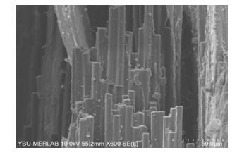
Figure 12: SEM image of CF/PEEK after the fracture.
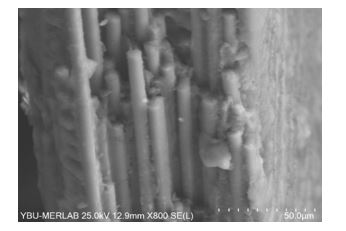
Figure 13: SEM image of GF/PP after the fracture.
Compression Test Results
An understanding of compressive properties is crucial to the development of improved composite materials and is a design limiting parameter [22]. Types of composites which are including CF reinforced PEEK and GF reinforced PP were subjected to compression loading in accordance with ASTM D 3410 standard. Hence, compressive strength, compressive modulus, elongation, and microstructure at the failure region were investigated by SEM analysis.
Compressive modulus and elongation were calculated according to the obtained experimental compressive strength and extension data as shown in Table 6 & 7.
Results were both acceptable and consistent by the reason of the fact that the influence of the test operator and compression jig has a great effect on the measured strength properties. The quality of the test results can often be judged by the coefficients of variation in strength and modulus and the failure modes of the test specimens. In determining the coefficient of variation (CoV) which gives the degree of variability of obtained data of testing was calculated as the ratio of the standard deviation σ to the mean μ in the aerospace industry. Considering of the results of seven samples, the percentage of CoV were computed as 7.65% and 4.08% for CF/PEEK and GF/PP, respectively. These results were acceptable in the aerospace industry so that this coefficient of variation has to be less than 10%.
The overall fracture occurred almost in the middle of the gauge section in the form of fiber breakage and axial splitting. The average compressive strengths of CF/PEEK and GF/PP are 528.9 and 222.4 MPa, respectively. It was also contributed to achieving valid compressive failures within the specimen gauge section that the use of 45° and 90° plies as outer layers reduced dramatically the tab stress concentration. In reference to these tables, whereas compressive strength was found ranging from 487 MPa to 583 MPa for CF/PEEK, it was obtained at 214MPa-238MPa for GF/PP. It can be clearly seen that compressive strength increases with the continuously increasing load as expected, except for 4.59kN belonging to the second specimen due to the higher content of manufacturing defects like delamination, voids or ply/fiber waviness maybe existence. Besides, the fiber direction compression strength of a PMC is highly dependent on the polymer matrix material’s ability to support the reinforcing fibers and resist buckling under compression loading. Comparison of 0º, stacking sequence [±45/0/90/±45/0/90]s, 90º orientation with 16 plies UD CF/PEEK samples plies are given in Table 8. The maximum results of strength and modulus were obtained in 0º orientation for CF/PEEK. By contrast with the smallest strength result was seen in 90º orientation. When the composites were compared with respect to the compressive strength, the CF/PEEK composites at 0° orientation had better performances rather than oriented in more than one direction, inherently having higher in the direction parallel to fiber with the comparison of the direction perpendicular to fiber. Therefore, it can be obviously said that when the samples were evaluated accordingly to effect of the stacking sequence that CF/PEEK with stacking sequenced had as not higher as in the 0° orientation. Nevertheless [±45°/0°/90°/±45°/0°/90°] oriented plies were preferred in which design criteria and manufacturing concerns were considered.
After the compression tests, failure zones in specimens were selected and examined by the SEM. In the examination of SEM images, classifications basically summarized into matrix cracks, initiation, and propagation of delamination, fiber micro buckling, and fiber breakage. Crack initiated and propagated along the fiber direction as shown in Figure 14.
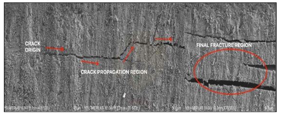
Figure 14: SEM image of crack initiations and propagation for CF/PEEK.
The delamination patterns were seen in different size, shape, and orientation at different laminate interfaces, particularly UD composites with the stacking sequences. The fiber/matrix interface properties and laminate configuration also found to play an important role in determining the shape and extent of damage, which, in turn, is related to the damage resistance of the composite. Matrix cracks and fiber fractures were also observed in a different manner in each layer. Light deformations were observed primarily in the compression region during under compressive load. Only the main cracks and sub cracks have existed interior surface as illustrated in Figure 15.
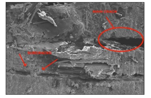
Figure 15: SEM image of main crack and sub cracks for CF/PEEK.
It can be concluded that the ductility of the matrix was prevented the further expansion of the crack, and there is no compression crack on the upper surface. With thermoplastic composites (TPC), the fibers may be more durable in the failure zone as a result of the high stiffness of the matrix. In the manufacturing process, which is hand layup by followed autoclaving, it has been shown that there is delamination, porosity, and inclusion were observed on the cross-section of the specimens due to labor-intensive and operator’s skill. However, distortion occurred in neither CF/PEEK nor GF/PP thanks to stacking sequence and cure cycles as expected. The thermoforming process which was carried out at various temperatures was optimized, the best product was obtained at above approximately 50ºC of melting temperature of the materials. The abovementioned experiments with quasi-isotropic UD CF/PEEK and GF/PP composites showed a clear difference in formability as indicated in the preceding Figure 3. These differences were relevant to process parameters which are temperature, pressure and required time. In other words, it can be said that still knowledge of the long-time performance and especially processing condition is lacking. In addition, alignment between the male and female mold was affected by the GF/PP final product. With the correction of these problems, it was obtained close to the desired shape in the UD CF/PEEK. Moreover, the absence of a blank holder was caused the slippage between the female tool and the blank. Many wrinkles had developed where near curved areas for the considered UD composites. The inappropriate forming tool may lead to those defects. Quality of the formed parts can be improved up that replaced the tool with an optimized one with respect to formability. GF/PP samples that have 8 plies specimens with the orientation of [±45º/0º/90º]s and CF/PEEK samples have 16 plies specimens with the stacking sequences of [±45º/0º/90º/±45º/0º/90º]s were tested mechanically. With respect to all the mechanical testing, UD 0º oriented both material samples have shown better performance than the other samples which has stacking sequences. By contrast, minimum strength values were seen at 90º orientation. When examined the microstructure of material after the tensile testing, it showed that both materials, fibers and polymer matrix, were well connected. As evidence of this, breakage was occurred both in the matrix and fibers concurrently. In the compression testing, test operator and compression jig had a great effect on the measured strength properties, considering specimens without any tabs. Results of testing are acceptable in the aerospace industry via that coefficient of variation was less than 10%. When the temperature of CF/PEEK and GF/PP blank was increased by preheating, the formability of both composites was enhanced. Wrinkles can be avoided with the use of tabs and fixtures, which are necessary to avoid slippage between the die and the specimen [23].
Conclusion
In this study, the use of thermoplastic composite materials mainly in aircraft structures have been investigated by utilizing press forming process for CF/PEEK and GF/PP thermoplastic composite materials. Following results were achieved.
1. The best formed product is achieved at approximately 50ºC above melting temperature of the material.
2. Both UD CF/PEEK and GF/PP materials can easily be used for possible aircraft structures.
3. UD CF/PEEK was found appropriate in the use of not only secondary structures but also for primary structures.
Acknowledgment
We greatly appreciate Dr. Ilyas Kacar and Nigde Omer Halisdemir University and Team of Technology Management Department at Turkish Aerospace Industries, Inc. for their support.
References
- Ghori SW, Siakeng R, Rasheed M, Saba N, Jawaid M (2018) The role of advanced polymer materials in aerospace. Sustainable Composites for Aerospace Applications p. 19–34.
- Malone LJ, Dolter T (2010) Basic concepts of chemistry. 8th ed. John Wiley & Sons, Inc; New York: pp. 726.
- Wang P, Hamila N, Boisse P (2013) Thermoforming simulation of multilayer composites with continuous fibres and thermoplastic matrix. Compos Part B Eng 52: 127–136.
- Offringa AR (1996) Thermoplastic composites – Rapid processing applications. Compos Part A Appl Sci Manuf 27(4): 329–336.
- Slange TK (2019) Rapid Manufacturing of Tailored Thermoplastic Composites by Automated Lay-up and Stamp Forming A Study on the Consolidation Mechanisms. University of Twente.
- Saraiva F (2017) Development of press forming techniques for thermoplastic composites: Investigation of a multiple step approach. TUDelft p. 103.
- (2020) Dutch Thermoplastic Composites.
- De Luca P, Lefébure P, Pickett AK (1998) Numerical and experimental investigation of some press forming parameters of two fibre reinforced thermoplastics: APC2-AS4 and PEI-CETEX. Compos Part A Appl Sci Manuf 29(1–2): 101–110.
- Ben Moore (2002) In-Cycle Control of the Thermoforming Reheat Process. pp. 132.
- Xie N (2018) NDT-based Performance Prediction for Wrinkled Composites under Compressive Load. University of Bristol pp. 1–220.
- Leterrier Y, G Sell C (1994) Formation and elimination of voids during the processing of thermoplastic of matrix composites. Polym Compos 15(2): 101–105.
- Ye L, Chen ZR, Lu M, Hou M (2005) De-consolidation and re-consolidation in CF/PPS thermoplastic matrix composites. Compos Part A Appl Sci Manuf 36(7): 915–922.
- Gröschel C, Drummer D (2014) The influence of moisture and laminate setup on the de-consolidation behavior of PA6/GF thermoplastic matrix composites. Int Polym Process 29(5): 660–668.
- Meng Q, Wang Z (2016) Micromechanical Modeling of Impact Damage Mechanisms in Unidirectional Composite Laminates. Appl Compos Mater 23(6): 1099–1116.
- Lévesque M, Gilchrist MD, Fisa B (2003) A theoretical study of the tensile test for highly anisotropic composite materials. ASTM Spec Tech Publ 1436: 320–335.
- Miracle DB, Donaldson SL (2001) ASM Handbook, Composites. ASM International. 21: 2605.
- Yıllıkçı K, Findik F (2013) A Survey of Aircraft Materials: Design for Airworthiness and Sustainability. Period Eng Nat Sci 1(1): 8–33.
- British Standard (1995) BSEN2561 – Carbon fibre reinforced plastics – Unidirectional laminates – Tensile test parallel to the fibre direction. British Standard Publication.
- Ghaffari S, Makeev A, Seon G, Cole DP, Magagnosc DJ, et al. (2020) Understanding compressive strength improvement of high modulus carbon-fiber reinforced polymeric composites through fiber-matrix interface characterization. Mater Des 193: 108798.
- Amjadi M, Fatemi A (2020) Multiaxial fatigue behavior of thermoplastics including mean stress and notch effects: Experiments and modeling. Int J Fatigue 136: 105571.
- ASTM (2016) ASTMD3410 – Standard Test Method for Compressive Properties of Polymer Matrix Composite Materials. ASTM Int p. 1–13.
- Chen L, Peng S, Liu J, Liu H, Chen L et al. (2020) Compressive response of multi-layered thermoplastic composite corrugated sandwich panels: Modelling and experiments. Compos Part B Eng 189: 107899.
- Liang B, Hamila N, Peillon M, Boisse P (2014) Analysis of thermoplastic prepreg bending stiffness during manufacturing and of its influence on wrinkling simulations. Compos Part A Appl Sci Manuf 67: 111–122.